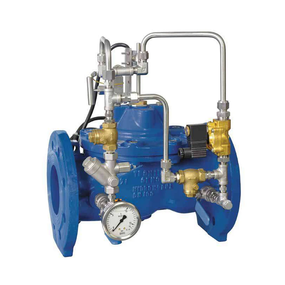
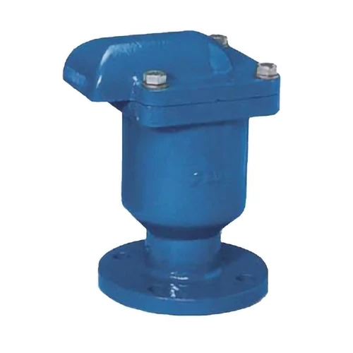
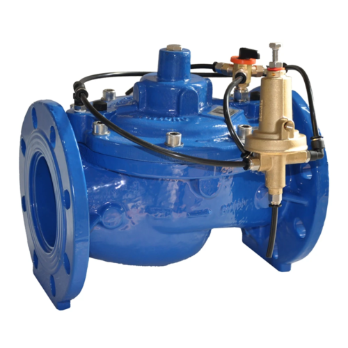
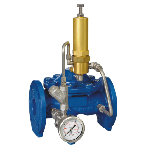
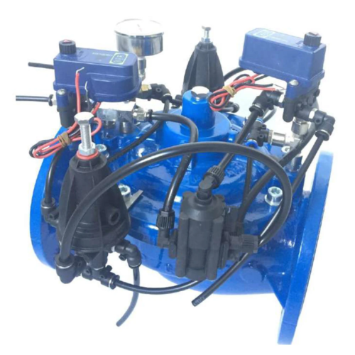
Hydromodul Pump Control Valve
WORKING CONDITIONS
The modulating float control valve GAL is designed to automatically mantain a constant reservoir level.
The valve is equipped with a modulating float pilot, mounted on tank, that opens gradually the valve when the water level goes down the maximum value.
INSTALLATION
- Prepare the pipe leaving the right distance between the flanges, the threaded or grooved connections.
- Clean the pipeline to avoid the entrance of extraneous materials inside the valve.
- Install the valve putting the arrow on the body in the same direction of the water flow.
- Don’t weld on the pipe near the valve in order to avoid any diaphragm damage.
- Install the float pilot near the reservoir manhole, in a still water place or inside the tank.
- Set the floater level for the reservoir.
- Fix the float to the reservoir wall, or other stable element, ensuring the float will remain correctly oriented.
- Anchor the float arm position by tightening the arm base screws.
- Follow the scheme for connecting the floater to the main valve.
USE INSTRUCTION
- Check that the connections between the float pilot and the main valve follow the scheme of the constructor.
- Open the onoff valve N°2 and N°6 of the hydraulic circuit.
- Check that the upstream pressure doesn’t fall down below 1 bar, otherwise the valve may not work.
- Open the water to the pipeline. Let open the valve checking that the float control pilot is in its lower position and fill the reservoir.
- Once the reservoir is full, check the correct functioning and the closing of the float pilot.
- The hydraulic circuit is equipped with a needle valve that regulate the opening speed. Tamper it damage the valve and generates a warranty loss.
- During the starting phase, the presence of air in the control chamber could influence the correct operation of the valve. In such case in order to totally evacuate the trapped air proceed as follows:
- during the reservoir filling, move the float arm
- manually to its upper position, forcing the valve to close, then to its lower position, forcing the valve to open.
- at each positions, vent air from the valve control
- circuit by loosening the tube fitting at the highest point on the valve and at the floater pilot port, allowing the air to bleed.
- Then retighten the fittings bolts.
MAINTENANCE
Rubber and elastomeric components must be checked and substitute periodically, about each 2 year, especially in case of damage due to solid particles inside the flow.
The components of the hydraulic circuit must be checked and the filter cleaned in case of need. The frequence of the checks depends of the application.
MAIN CHARACTERISTICS
The valve shall be made with high hydrodunamics section globe body, without stagnation pockets (conical, low pressure loss type), the main valve body and cover shall be made in standard ductile cast iron casting GS400/GGG40 (carbon steel casting on request) and the valve body and
cover shall be protected by 200°C furnace polyurethan resin powder paiting with 150 micron of minimum guaranteed thickness.
The seal seat, stem and return spring shall be made in stainless steel for better cavitation resistance, and the plunger seal disc shall be entirely guided and indipendent of the seal seat.

